
GPIO is a fundamental technology in the world of electronics. It stands for General Purpose Input/Output and is used for controlling and communicating with external devices. It provides a flexible interface for interacting with external devices, enabling input and output operations. In this article, we will delve into the various programming techniques and concepts related to GPIO, equipping you with the knowledge to harness its power effectively. We’ll also answer common questions about GPIO, including whether computers have GPIO and USB use GPIO. By the end of this post, you’ll have a better understanding of GPIO and its applications in the field of electronics.
What is GPIO in Microcontroller?
The full form of GPIO is call General Purpose Input/Output. It is a term commonly used in electronics and computing. GPIO is a flexible way of controlling and monitoring the flow of electrical signals in a device. It refers to a type of pin or port on a microcontroller or other hardware that can be used for both input and output functions.
Regarding port standards like USB or DVI, each pin within the connection serves a predetermined purpose set by the standard’s governing body. However, the General Purpose Input/Output pins differ. With GPIO, you can determine what each pin does. It’s worth noting that different types of pins are available on the GPIO array.
For instance, if you’re using a Raspberry Pi, you’ll come across several types of pins:
- There are pins that provide power at standard voltages, such as 3.3V or 5V. These pins are useful for powering external devices without a power source, such as an LED.
- There are ground pins that don’t output power but are essential for completing certain circuits. General Purpose Input/Output pins are the ones that can be configured to send or receive electrical signals.
- There are special-purpose pins that vary depending on the specific GPIO in use.
In simpler terms, GPIO pins can be used to control various electronic components and sensors. You can use it to provide a simple, flexible interface with other hardware components. They can receive input signals, such as a button press. You also can use it to output signals, such as driving an LED. This allows a microcontroller to interact with its environment and perform various tasks. This includes everything from collecting data to controlling the robot. The flexibility of GPIO pins is one of their biggest advantages. This is because they can be easily reconfigured for different purposes.
GPIO pins are commonly used in embedded systems, such as microcontrollers and single-board computers like the Raspberry Pi. These devices often have a limited number of pins. So GPIO allows them to interface with other components and sensors without requiring additional hardware.
How does GPIO Work?
GPIO allows devices to communicate with the physical world by controlling and monitoring electrical signals. General Purpose Input/Output pins are used to send and receive digital signals, which a microcontroller or other electronic device can interpret.
It can be used to drive an external circuit with a digital signal when a GPIO pin is set to output mode. It can be used to read the state of a switch or sensor when set to input mode.
The digital signals sent and received by GPIO pins are represented by binary values of 0 and 1, which correspond to low and high voltages, respectively. The state of a GPIO pin can be set or read using programming instructions in the software running on the device.
GPIO pins can be connected to a wide variety of external devices. These include sensors, switches, LEDs, motors, and more. By using GPIO, developers can create complex electronic systems that interact with the physical world in a variety of ways.
GPIO Programming Basics
Configuring GPIO Pins
To use GPIO, you must configure the pins according to your requirements. This involves setting the pin direction (input or output) and other parameters like pull-up or pull-down resistors. Most microcontrollers provide registers or libraries to simplify this process.
Reading Input Signals
Reading input signals from GPIO pins involves checking the logical state of the pin. The pin can be read as a digital high (1) or low (0), depending on the voltage level received. This information can be used to trigger actions or make decisions within the program.
Writing Output Signals
When configuring a GPIO pin as an output, you can write a logically high or low value. This, in turn, affects the connected component. For instance, driving a logical high to an LED pin would turn it on, while a logical low would turn it off.
GPIO Interrupts
Interrupts allow the microcontroller to respond to external events promptly. GPIO interrupts can be configured to trigger specific actions when certain conditions are met. For example, an interrupt can be generated when a button connected to a GPIO pin is pressed or a sensor detects a particular event.
GPIO Programming Languages
GPIO can be programmed using a variety of programming languages. This depends on your needs and preferences. Here are some of the most common programming languages used for GPIO:
Python
Python is a popular language for working with GPIO. This is thanks to its simple syntax and powerful libraries like RPi.GPIO and GPIO Zero.
C/C++
C and C++ are low-level programming languages that offer high performance and precise control over GPIO pins.
JavaScript
JavaScript can be used for GPIO programming on web-based applications or through Node.js, a runtime environment for JavaScript.
Bash Scripting
Bash scripting is a simple way to control GPIO pins through the Linux command line. This makes it a great option for automation and scripting tasks.
Scratch
Scratch is a block-based visual programming language that can be used to control GPIO pins on the Raspberry Pi.
What is the Difference Between GPIO and Port?
GPIO and port are both types of interfaces used in electronics. However, they differ in their functionality and purpose. GPIO is used for controlling and monitoring external devices, while ports are used for transferring data between devices. While there may be some overlap in their functionality, they serve distinct purposes in electronics.
Here’s a Table Summarizing the Main Differences between GPIO and Port:
| Feature | GPIO | Port |
|---|---|---|
| Full Form | General Purpose Input/Output | N/A |
| Functionality | Control and monitor external devices | Transfer data between devices |
| Usage | Commonly used in microcontrollers and single-board computers | Used to connect devices like printers, monitors, and keyboards to computers |
| Input/Output | Both Input and Output | Mostly Output |
| Number of Pins | Fewer Pins | More Pins |
| Voltage Level | Low Voltage | High Voltage |
| Programming | Need programming to control | Mostly Plug and Play |
| Signal Processing | Direct signal processing | Signal processed through a controller or chipset |
| Examples | Used in microcontrollers and single-board computers | USB, Ethernet, HDMI, VGA |
What is GPIO Used for?
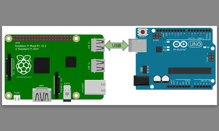
If you’re new to GPIO projects and want to start with your Raspberry Pi, you can begin with a simple power button. Unlike the standard board that lacks a power button, you can create one using GPIO pins that initiates a shutdown or reboot sequence.
On the other hand, if you’re interested in programmable devices that can control other equipment, the Arduino microcontroller is a popular option with GPIO. Unlike the Raspberry Pi, the Arduino is not a full-fledged computer but a versatile device that can be programmed to perform various tasks. For instance, you can connect a light sensor to an Arduino and program it to automatically turn on your garden lights when the sun goes down. Arduinos have been instrumental in opening up the world of robotics and invention to people who may not have had the opportunity to explore engineering and programming otherwise.
GPIO is used for a wide range of electronic projects and applications. It provides a flexible way to control and monitor external devices. This makes it an essential component of many electronic systems. Here are some of the main applications of GPIO:
What is GPIO Used for Sensor Monitoring
You can use GPIO to read sensor signals and detect environmental changes. For example, a temperature sensor could be connected to a GPIO pin to monitor the temperature of a room.
What is GPIO Used for Device Control
GPIO can control external devices such as LEDs and motors. It allows developers to easily interface with hardware components, turning them on or off and controlling their behavior.
What is GPIO Used for Communication
GPIO can be used for communication between devices. For example, two devices could be connected using GPIO pins to transfer data between them.
What is GPIO Used for Custom Interfaces
You can use GPIO to create unique input/output interfaces for electronic devices by connecting custom components to the GPIO pins. This allows for personalized and specific control and interaction with the device.
What is GPIO Used for Home Automation
GPIO can control lights, appliances, and HVAC systems. It is used to automate homes by connecting the devices to the GPIO pins of a microcontroller or single-board computer, such as the Raspberry Pi. GPIO pins can be programmed to turn devices on or off, adjust temperature settings, and monitor energy usage. This allows customized home automation solutions that save energy and increase convenience.
What Devices Use GPIO?
GPIO is widely used in electronics for controlling and monitoring external devices. Popular devices like Raspberry Pi and Arduino use GPIO pins for interacting with the physical world. GPIO is used in sensors, switches, industrial control systems, home automation devices, and medical equipment due to its flexibility and ease of use. Its wide usage makes it an essential tool in the field of electronics.
Dangers of GPIOs
In addition to connecting your GPIO pins to external circuit boards or devices, your computer or microcontroller needs software to understand the signals coming through the GPIO interface. This software is often custom-written, especially in the case of Raspberry Pi systems, where Python is a popular choice for programming GPIO controllers.
To take control of the GPIO system on Raspberry Pi, you can use two Python modules: RPi.GPIO and gpiozero. These modules allow you to send signals to the GPIO pins or listen in on incoming signals, putting you in complete control of your GPIO projects.
For Arduino microcontrollers, the programming language is specific to the device, making it easy to assemble projects. However, you can also use a version of Python called MicroPython to program Arduino boards. This opens up even more possibilities for your projects, allowing you to leverage the simplicity of Python while taking advantage of the power of Arduino.
How to Use GPIO
In addition to connecting your GPIO pins to external circuit boards or devices, your computer or microcontroller needs software to understand the signals coming through the GPIO interface. This software is often custom-written, especially in the case of Raspberry Pi systems, where Python is a popular choice for programming GPIO controllers.
To take control of the GPIO system on Raspberry Pi, you can use two Python modules: RPi.GPIO and gpiozero. These modules allow you to send signals to the GPIO pins or listen in on incoming signals, putting you in complete control of your GPIO projects.
For Arduino microcontrollers, the programming language is specific to the device, making it easy to assemble projects. However, you can also use a version of Python called MicroPython to program Arduino boards. This opens up even more possibilities for your projects, allowing you to leverage the simplicity of Python while taking advantage of the power of Arduino.
On the other hand, using GPIO requires a basic understanding of electronics and programming. Here are the general steps to using GPIO:
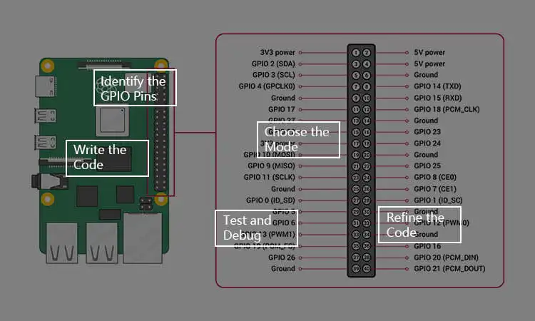
Identify the GPIO Pins
Most microcontrollers and single-board computers have pins specifically designated for GPIO. These pins will be labeled with numbers or other identifiers. And their location will be specified in the device’s documentation.
Choose the Mode
GPIO pins can be set to either input or output mode, depending on the application. Input mode lets the device read data from external sensors or other input devices. Output mode allows the device to control external devices.
Write the Code
Once the pins are identified, and the mode is chosen, the next step is to write the code to control the GPIO pins. This can be done using a programming language like Python or C or through the device’s built-in tools.
Test and Debug
Once the code is written, testing it to ensure that the GPIO pins are correctly working is essential. This can involve connecting external devices like LEDs or sensors to the pins and observing their behavior.
Refine the Code
If there are any issues with the GPIO pins, the code may need to be refined and debugged. This can involve adjusting settings like the pin mode. It also can involve adding error handling code to deal with unexpected input.
Common Challenges and Troubleshooting Tips
GPIO can sometimes encounter problems or fail to work as expected, like any electronic component. Here are some tips for troubleshooting GPIO issues:
- Troubleshooting Question 1: Insufficient Current Drive:
Solution 1: Sometimes, GPIO pins might not be able to provide enough current to drive certain components. External components like transistors or drivers can amplify the current in such cases. - Troubleshooting Question 2: Signal integrity issues:
Solution 2: Long wires or noisy environments can lead to signal integrity problems. To mitigate this, consider using shielded cables, adding filtering components, or employing proper grounding techniques. - Troubleshooting Question 3: Pin conflicts:
Solution 3: Multiple peripherals might need access to the same GPIO pin in complex projects. It’s crucial to ensure that there are no pin conflicts and that each peripheral is properly configured.
Understanding GPIO programming techniques is crucial for effectively utilizing the capabilities of microcontrollers and embedded systems. You can interact with the external world and control various components by configuring GPIO pins, reading input signals, writing output signals, and utilizing interrupts. Additionally, considering performance optimization, troubleshooting common challenges, and following best practices ensure reliable and efficient GPIO operations.
Read More: The Role of a GPIO Controller in Embedded Systems
- Pin: A physical connection point on a microcontroller or other device that can be used as a GPIO. Each pin has a number or label that identifies it.
- Input: A GPIO pin configured to receive signals from an external device or sensor. Input pins are often used to read button presses, temperature sensors, and other data types.
- Output: A GPIO pin configured to send signals to an external device or component. Output pins often control LEDs, motors, and other device types.
- High/Low: A binary state indicating whether a GPIO pin is receiving or sending a signal. A high signal (also known as “1”) is a voltage level that is above a certain threshold, while a low signal (also known as “0”) is a voltage level that is below a certain threshold.
- PWM: Pulse Width Modulation is a technique that uses a series of pulses of varying widths to simulate an analog signal. PWM is often used to control the brightness of LEDs or the speed of motors.
- Bus: A collection of GPIO pins to communicate with a specific device or component. Buses are often used to connect external sensors or modules to a microcontroller.
- Tri-state: A state in which a GPIO pin can be configured as an input, output, or high-impedance (i.e., not connected to anything). Bus systems often use tr-state pins to avoid conflicts between multiple devices.
- Bit-banging: A technique that manually controls individual GPIO pins to simulate a communication protocol, such as SPI or I2C. Bit-banging can be useful when a microcontroller lacks dedicated hardware for a specific protocol.
More Question About GPIO
-
Q1: Can I use any pin as GPIO on a microcontroller?
A1: Yes, microcontrollers typically offer a set of pins that can be used as GPIO. However, certain pins might have additional functionalities or restrictions. Consult the microcontroller’s datasheet or reference manual to identify GPIO-capable pins.
-
Q2: How do I choose the appropriate GPIO pin for my application?
A2: When selecting a GPIO pin, consider the required voltage levels, current capabilities, and any specific functionalities needed for your application. Additionally, ensure that the chosen pin does not conflict with other peripherals or pins.
-
Q3: Can I use GPIO pins for analog signals?
A3: GPIO pins are primarily designed for digital signals, but some microcontrollers can configure certain pins as analog inputs or outputs. Check the specifications of your microcontroller to determine if analog functionality is available on GPIO pins.
-
Q4: Are there any limitations on the number of GPIO pins I can use?
A4: The number of available GPIO pins depends on your specific microcontroller. Different microcontrollers offer varying numbers of GPIO pins, ranging from a few to dozens or more. Refer to your microcontroller’s datasheet or reference manual for the exact number of GPIO pins available.
-
Q5: How fast can I toggle GPIO pins?
A5: The speed you can toggle GPIO pins depends on the specific microcontroller and clock frequency. Generally, microcontrollers can toggle GPIO pins at speeds ranging from a few kilohertz to several megahertz. Consult the microcontroller’s documentation for precise timing specifications.
-
Q6: Can I connect multiple devices to a single GPIO pin?
A6: In most cases, connecting multiple devices directly to a single GPIO pin is not recommended. Doing so can lead to conflicts, signal degradation, and increased power consumption. Instead, consider using additional components like multiplexers or bus protocols to manage multiple devices effectively.
-
Q7: Are there any precautions I should take when using GPIO pins?
A7: When working with GPIO pins, carefully handling them is essential to prevent accidental short circuits or damage. Ensure that voltages and currents applied to the pins are within the specified limits. Proper grounding techniques and ESD (Electrostatic Discharge) precautions should also be followed to protect the microcontroller and connected devices.
 Guide")


