
The crankshaft position sensor is an essential component of a vehicle’s engine system. It provides information to the engine control module, allowing the engine to operate efficiently. However, it can cause several issues when the sensor fails. Including stalling, misfires, and difficulty starting the car. This article will discuss how to test a 3 wire crank sensor using a multimeter. We will provide step-by-step instructions and useful tips to help you diagnose any issues with your vehicle’s crankshaft position sensor.
What is 3 Wire Crank Sensor?
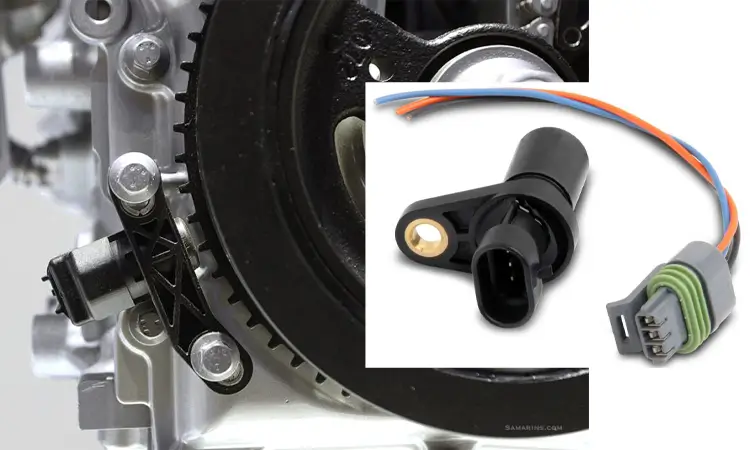
A 3 wire sensor is a type of sensor that is commonly used in automotive applications to measure various engine parameters. Including the position of the crankshaft and camshaft. It is also known as a Hall-effect sensor.
The three-wire sensor consists of three wires: a power, ground, and signal wire. The power wire supplies the sensor with the necessary voltage. The ground wire provides a return path for the current. And the signal wire carries the output signal.
The 3-wire sensor uses a magnetic field to detect the position of a rotating object, such as a crankshaft or camshaft. When the object rotates, the sensor detects a magnetic field, which sends a signal to the engine control module (ECM).
The 3 wire sensor is widely used in modern automotive engines for its accuracy, reliability, and low cost. It is also easy to install and maintain, making it a popular choice for many vehicle manufacturers.
3 Wire Crank Sensor Type
Many types of 3 wire sensors are available, each designed to measure a different parameter. Some common types of 3-wire sensors used in automotive applications include:
- Crankshaft position sensors – These sensors measure the position and speed of the engine’s crankshaft and are used for engine control and timing.
- Throttle position sensors – These sensors measure the position of the throttle valve in the engine’s intake manifold and are used for engine control and fuel injection.
- Oxygen sensors – These sensors measure the amount of oxygen in the engine’s exhaust gases and are used for fuel control and emissions monitoring.
- Coolant temperature sensors – These sensors measure the temperature of the engine’s coolant and are used for engine control and cooling system monitoring.
- Mass airflow sensors – These sensors measure the amount of air entering the engine and are used for fuel control and emissions monitoring.
Other types of 3 wire sensors include pressure, speed, and position sensors for various components in the vehicle, such as the transmission, suspension, and steering. The specific type of sensor used will depend on the vehicle’s make and model and the parameter being measured.
What does the 3 Wire Sensor Consist of?
A 3 wire sensor consists of three basic components: a power supply, a ground connection, and a signal output.
The power supply wire provides the necessary voltage to operate the sensor, typically between 5-12 volts.
The ground wire provides a return path for the current to flow to the vehicle’s electrical system.
The signal output wire carries the sensor’s output signal to the vehicle’s ECM or another monitoring device.
Inside the sensor, there is a magnet and a Hall-effect sensor that detect the position of a rotating object, such as the crankshaft or camshaft in an engine.
It generates a magnetic field when an object rotates, which a Hall-effect sensor detects. Then it sends a signal to the ECM or other monitoring device.
The 3 wire sensor is a critical component in many engine management systems and is crucial in maintaining proper engine performance.
How does a 3 Wire Sensor Work?
A 3 wire sensor detects changes in a magnetic field created by a rotating object, such as a crankshaft or camshaft. When the rotating object passes, the sensor detects the sensor, the magnetic field changes, and this changes.
The sensor uses the Hall-effect principle to detect the magnetic field. When a magnetic field is applied to a Hall-effect sensor, it produces a voltage across the sensor. This voltage is proportional to the strength of the magnetic field.
The sensor output is an electrical signal sent to the ECM or other control systems. The signal is usually a square wave with a frequency proportional to the rotating object’s speed.
The ECM uses signals from a 3-wire sensor to determine the position of rotating objects. It can also control engine functions such as ignition timing, fuel injection, and valve timing.
Symptoms of a Faulty Crankshaft Position Sensor
A faulty crankshaft position sensor can cause various problems for a vehicle’s engine system. It is essential to recognize the symptoms of a faulty sensor to avoid further damage to the engine. Here are some common symptoms of a faulty crankshaft position sensor:
- Engine stalling: A faulty sensor can cause the engine to stall while driving, making it difficult to restart.
- Difficulty starting: A bad sensor can make it challenging to start the engine, causing the engine to crank without starting.
- Rough idling: A faulty sensor can cause the engine to idle roughly or unevenly, leading to a rough ride.
- Reduced engine performance: If the engine control module does not receive accurate information from the crankshaft position sensor, the engine may not perform optimally.
- Poor acceleration: A bad sensor can result in poor acceleration, making it challenging to drive at higher speeds.
- Misfiring: A faulty sensor can cause the engine to misfire, decreasing power and performance.
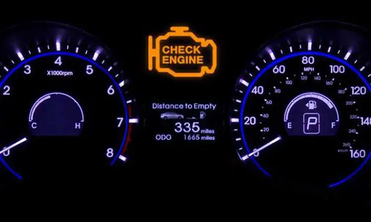
- Check Engine Light: A faulty sensor can trigger the Check Engine Light to come on, indicating a problem with the engine system.
- Poor fuel economy: A bad sensor can cause the engine to run inefficiently, resulting in poor fuel economy and increased emissions.
Transmission issues: In some cases, a faulty crankshaft position sensor can cause problems with the transmission, such as shifting issues or hesitation.
If any of these symptoms occur, it is essential to have the crankshaft position sensor inspected and tested by a professional mechanic. A faulty sensor can cause further damage to the engine if not addressed promptly, leading to costly repairs. By recognizing the symptoms of a faulty sensor and addressing the issue promptly, vehicle owners can ensure that their engine runs smoothly and efficiently.
How to Test 3 wire Crank Sensor with Multimeter
Testing a 3 wire crank sensor with a multimeter is a straightforward process that can help diagnose problems with the sensor. Here are the steps to follow:
- Prepare the multimeter: Set the multimeter to measure resistance and connect the test leads.
- Locate the sensor: The crankshaft position sensor is on the engine block.
- Disconnect the sensor: Disconnect the electrical connector from the sensor.
- Measure resistance: Connect one of the tests leads to the sensor’s signal wire and the other test lead to the ground wire. The multimeter should display a resistance reading within the sensor’s specified range.
- Check power and ground: Connect one of the tests to the sensor’s power wire and the other to the ground wire. The multimeter should display a voltage reading within the sensor’s specified range.
- Bench test the sensor: If the sensor’s resistance and voltage readings are within the specified range, the sensor may still be faulty. A bench test can confirm if the sensor is functioning correctly.
Following these steps, vehicle owners can determine if the crankshaft position sensor works correctly. It is essential to ensure that the multimeter is set to measure resistance and voltage correctly and that the sensor’s readings fall within the specified range. If the sensor is faulty, it should be replaced promptly to avoid further damage to the engine. Testing the sensor with a multimeter is a cost-effective and efficient way to diagnose problems with the engine system.
How to Bench Test 3 Wire Crank Sensor with Multimeter
Bench testing a three-wire crank sensor with a multimeter is a more detailed way to diagnose problems with the sensor. Here are the steps to follow:
- First, remove the sensor from the engine and clean it with a solvent.
- Connect the sensor to a power source, typically a 12-volt battery, and a signal generator that produces a square wave.
- Set the signal generator to produce a signal at the frequency and amplitude specified by the vehicle’s service manual.
- Connect the oscilloscope to the sensor output and set it to display the signal waveform.
- Rotate the sensor and observe the waveform on the oscilloscope. The waveform should be a square wave with a clear on-off transition.
- If the waveform is incorrect, adjust the signal generator and retest the sensor.
- Record and compare the waveform to the waveform specified by the vehicle’s service manual.
- If the waveform does not match the specification, the sensor may be faulty and should be replaced.
Bench testing a 3 wire crank sensor with a multimeter can provide more detailed information about the sensor’s performance than testing with a multimeter alone. However, it requires specialized equipment and expertise and should be performed by a professional mechanic.
Three-wire sensors are critical components in many industrial applications. Understanding how to test 3 wire crank sensors with a multimeter is essential to ensure proper functioning. Following the proper testing procedures makes it possible to diagnose and repair sensor issues before they cause significant problems.
Related Guide:
Science
- How Many Ohms Should a Crank Sensor Have?
The resistance of a crankshaft position sensor can vary depending on the specific make and model of the vehicle. However, a typical crankshaft position sensor should generally have a resistance of between 500 to 1500 ohms at room temperature (around 68-77°F or 20-25°C). This value may vary depending on the manufacturer’s specifications and the specific conditions of the engine. If you are experiencing issues with your vehicle’s crankshaft position sensor, it’s best to refer to the manufacturer’s specifications or consult a qualified mechanic for assistance.
- How Many Volts Should a Crank Sensor Have?
The voltage output of the crankshaft position sensor will vary depending on the vehicle’s specific make and model and the engine’s condition. Typically, a crankshaft position sensor will produce a voltage signal of between 0.2 and 5 volts AC (alternating current) or DC (direct current). This depends on the sensor’s design and the engine’s operating conditions.
What is the Difference Between a 2 Wire and 3 Wire Crank Sensor?
Here’s a table summarizing some of the main differences between 2-wire and 3-wire crankshaft position sensors:
| Feature | 2-Wire Sensor | 3-Wire Sensor |
|---|---|---|
| Number of wires | 2 | 3 |
| Signal output | AC voltage | Digital square wave |
| Signal quality | Lower quality due to electrical noise | Higher quality due to signal conditioning |
| Compatibility | May be less compatible with modern engine management systems | Widely compatible with modern engine management systems |
| Wiring | Requires separate power and ground wires | Power and ground wires are often integrated with the signal wire |
| Accuracy | May have lower accuracy due to signal noise | Generally more accurate due to signal conditioning |
| Cost | Typically less expensive | Typically more expensive |
- What is the Color Code for 3 Wire Sensor?
The color code for a 3-wire sensor can vary depending on the specific type of sensor and the manufacturer. However, in general, the following color codes are commonly used for 3-wire sensors:
- Red wire: Power or Positive (+)
- Black or brown wire: Ground or Negative (-)
- Blue or green wire: Signal or Output Press Tab to write more.
General Q&A About How to Test 3 Wire Crank Sensor with Multimeter
-
What tools do I need to test a 3 wire crank sensor with a multimeter?
To test a three wire crank sensor with a multimeter, you will need a multimeter, a wiring diagram for the vehicle, and a basic understanding of electrical circuits.
-
How do I determine which of the three wires is the signal wire?
The signal wire is typically the center wire of the three wire crank sensor. You can confirm this by referring to the wiring diagram for the vehicle.
-
What should I do if I am unable to identify the signal wire?
If you cannot identify the signal wire, consult the wiring diagram for the vehicle or seek assistance from a professional mechanic.
-
How do I perform a voltage test on the sensor?
To perform a voltage test on the sensor, connect the multimeter probes to the signal and ground wires, then crank the engine and observe the voltage reading.
-
What do I do if the sensor fails any of the tests?
If the sensor fails any tests, it may need to be replaced. Consult the service manual for the vehicle to determine the correct replacement procedure.
-
What is the purpose of a 3 wire crank sensor?
The purpose of a -wire crank sensor is to monitor the position and speed of the crankshaft and provide this information to the engine control module (ECM) to control engine performance.
-
What are some common symptoms of a faulty 3 wire crank sensor?
Common symptoms of a faulty 3-wire crank sensor include engine misfires, stalling, rough running, and difficulty starting.
-
Can a 3 wire crank sensor be tested without a multimeter?
Testing a 3 wire crank sensor may be possible using other diagnostic tools, such as an oscilloscope or scan tool. However, a multimeter is a commonly used tool for this type of testing.
-
How often should a 3 wire crank sensor be tested?
There is no set schedule for testing a 3 wire crank sensor. However, if you are experiencing engine performance issues, testing the sensor to diagnose the problem may be necessary.


 Guide")


